You breathe in as you run your fingers along the beautifully smoothen edges. Your eyes start to twinkle as you get closer, tilting your head to admire the sharpness of the cut.
Nothing can compare to a well-designed, quality cut laser part. The problem is, if your parts are not designed to deal with secondary processes such as folding and bending, all the beauty and benefits from laser cutting can be lost.
Here are our top tips for achieving the best results when bending or folding laser cut parts:
1. The fewer bend radii, the less tools setups you will need.
Avoid using different bend radius in a single part. The smallest inner bending radius should be of at least one material thickness. Generally, designing an inner radius equal to the material thickness will simplify your bend allowance calculations and avoid material fracture.
2. If the flange is too short, the part may fall into the die.
To avoid distortion of the part and damage to the operator or the tooling, make sure that the smallest flange is at least 4 times the material thickness plus the bending radius.
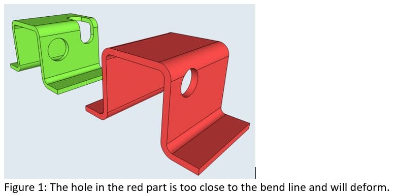
3. Avoid placing holes closer than 3 times the thickness plus 1 bending radius to the bend.
This will avoid deformed holes. If you need to place a hole or slot closer to the bend, it is better to extend these holes beyond the folding line for better results.

4. Allow some space between the chamfer end and the folding line.
When you need one or two chamfered ends in the flanges, the chamfer must leave enough room to accomplish a proper bend. Same 3 times thickness plus one bending radius rule apply.

5. Replace mounting holes with slots.
Whenever possible, in parts with multiple bends, mounting holes should be replaced by slots to allow for tolerance stacking.
6. Try to design parts as symmetric as possible.
This is to avoid parts bent in the wrong direction due to operator confusion.

7. Avoid designing small flanges on big parts.
These bends make manufacturing very difficult and labor intensive.
8. Check feasibility of successive bends.
When designing parts with successive bends, check the feasibility of the part because sometimes it is not possible to fit the already-bent part onto the die.

9. Place all the bends aligned in order.
If the part has several flanges in succession, it is best to place all the bends aligned in order to minimize readjustments during the bending process and save time.

10. Always design bends parallel to a side of the part.
For positioning purposes, try to always design bends parallel to a side of the part. Oblique bends are difficult to align and may result in rejected parts.
11. Include bend reliefs
Include bend reliefs (at least 1 thickness wide) on the sides of flanges to prevent the material from tearing or deforming on the flanges’ ends.

12. Bend perpendicular.
Where possible, bending perpendicular to the rolling direction of the material should be preferred. This will prevent fractures on hard materials.
13. Calculating flat pattern lengths.
Finally, when you design folded parts, and you are drawing the flat pattern yourself, you have two ways of calculating your flat patterns length. Depending on how you measure both legs of your bent part you will have to calculate either the Bend Allowance or the Bend Deduction.

The total flat length of the part (Lt) can be calculated as:
Lt = A + B – BD or,
Lt = A + B + BA
Bend Allowance
To calculate bend allowances we will use a K-factor that represents a ratio that represents the position of the neutral plane (the plane within the material that is neither compressed nor stretched when the material is bent) with respect to the thickness of the part.

K=t/T
To calculate Bend Allowances using the K-factor you can use the following formula:
Where;
BA: Bend Allowance
R: Inside bend radius
K: K-factor
T: Material thickness
T: distance from inside facto to neutral plane
a: bend angle in degrees.
Bend Deduction
To calculate the Bend Deduction:

This way you can calculate the total flat length using BA or BD.
To calculate the K-factor, the easiest way is to reverse engineer it. For that you can cut a strip of the material you need and make a 90º bend. Then measure both legs of the bend and calculate the Bend Deduction. Using the following formula, you can calculate the K-factor:

You can manually calculate the flat lengths or use your preferred CAD system to unfold the parts for you. In this case, you may input the K-factor you just calculated to give accurate dimensions for your parts given your particular tooling and material.
Felipe Luchaga
Director, Tempus Tools


